vCard
vCard
 Homemade by CVG
 My Homemade Apps
 Thingiverse
 Strava
XBee - Zigbee module
Zigbee is the de facto wireless communication standard in Wireless Sensor Networks these days. It’s a low-power communication stack that provides a way to create a meshed network of motes.
To ease the initial pain, I decided to start with a very nicely packed module, created within the realm of Arduino. The XBee ↗ family of modules are a cost-effective way of incorporating Zigbee into embedded systems.
The Goodies
Let’s start with the things we need to get started…
Hardware
Below is the list of hardware I bought to get started. I’ve included links to a reasonably priced reseller, but other sources are equally good or even cheaper.
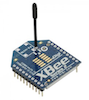
The XBee module come in two major flavors: Series 1 and Series 2. Series 2 implements the entire Zigbee standard and it’s therefore important to remember that you can’t mix the two series. I chose Series 2, which was also the choice of the book I used to get started.
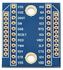
The XBee module’s pins are spaced at 2mm, which is not the same as the 1” spacing of regular through-hole boards. To be able to mount them on a breadboard or on a basic board, one needs an adapter. These adapters are too cheap not to buy and allow you to get started quickly. They (most of the time) come with both the female headers to fit the XBee aswel as male headers to prepare them to be mounted on regularly spaces boards.

Finally, although you are ready to go with two XBees, a very useful addition is a USB adapter. It’s almost a necessity to be able to configure and upload firmware to your module and it makes an easy way of connecting an XBee to your computer and control it from there.
Software
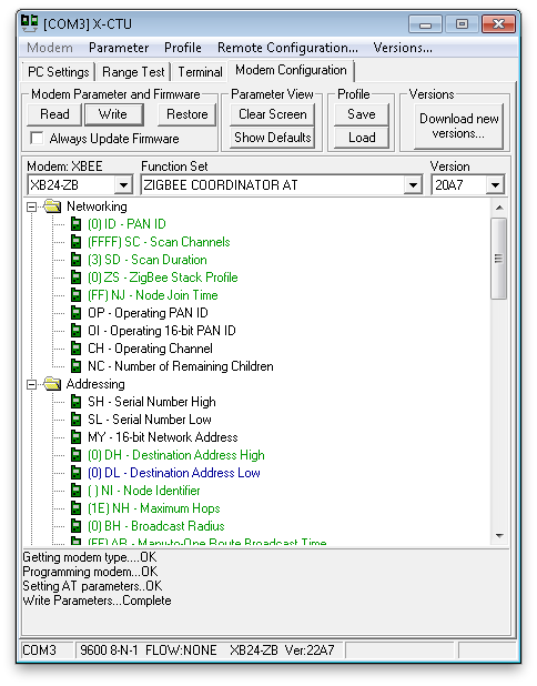
To be able to configure the XBee module, one needs the X-CTU ↗ provided by Digi. It’s a Windows only solution, which is a pity. I found references to non-Windows solutions, but along those also the comments that it’s not the real thing. So better launch that Windows partition or virtual machine.
Literature

Although the standard documentation of the XBee is pretty decent, I again consulted O’Reilly for some additional reading material. “Building Wireless Sensor Networks” introduces WSN through small projects based on the XBee module.
The book is aimed at very novice users, which makes it an easy and fast read. The examples gradually build up the complexity using realistic examples. Because not all material was of interest to me, I could skip large parts dealing with processing and setting up an internet-gateway. Overall the book presented me with the background information I needed to build my own way of using the XBee module.
It’s surely not a must and you will find most of the interesting information also through online sources, but I found it to be a good help and in the end it took me less than half a day to go through the parts that were interesting to me. The information on this page is to great extend what I wanted to recall later, but it surely doesn’t cover the entire book.
Transparent or API Mode
The XBee module provides two ways of interacting with the underlying Zigbee protocols: the (default) transparent mode and the API mode.
Choosing a mode requires a different firmware - mainly due to the size constraints of the XBee. The same goes for the role the mote will have in the network, as we will see below when I briefly introduce the Zigbee network topology.
Transparent Mode
In transparent mode, two module simply replace a serial (cable) connection. The module has a simple pair of Data In and Data Out pins which can be directly connected to the corresponding pins of a UART interface. So in a way, we can consider the XBee module - in transparent mode - a drop-in replacement for a MAX232 and attached serial cable. I’ll show this below as an example, starting from my MAX232 example.
The module behaves as a modem and responds to an attention request. This allows us to stop simply sending the exact characters we feed it, and access its configuration interface through a series of AT commands. We’ll use this interface in a minute when we configure our first set of XBees.
API Mode
Although it is super to have such a transparent mode, even with the ability to configure many parameters of the firmware, it still is not enough.
Simply sending characters over the wire is error-prone. We would have to implement our own transmission protocol to make sure that everything makes it to the other side as intended.
Another aspect is that of automated access to the configuration API. If we want to retrieve information from the XBee or give it commands to control its behavior, the manual approach simply doesn’t play nice.
Enter the API mode. When an XBee is in API mode, it no longer simply transmits whatever it receives. It now expects well formatted packets of information.
There are many different types of packets, ranging from simple transmission and receive packets to packets that give information about the operational status of the XBee and de messages that are transmitted.
If we for example introduce power management, by putting the XBee to sleep, we will see that we can’t simply rely on the transparent mode. We will need tools to check and make sure that the XBee is well awake, or rather put, is associated again and ready to send.
Concepts and Configuration
As with any network, we first need to configure the low-level networking setup. But let’s first summarize the layout of a typical Zigbee network.
Zigbee Networks
A Zigbee network consists of nodes. Each node can take on a specific task: that of a coordinator, a router or an end-node. There can be only one coordinator for a given Zigbee network. Routers and end-nodes are pretty much identical, give that a router can never be put to sleep, due to its task of routing messages between other nodes. Using these three types of nodes, a tree-like meshed network can be created, allowing end-nodes to send messages through routers and the coordinator to any other node.
Choosing a node type for an XBee, consists of booting up X-CTU and selecting the appropriate firmware.
Each Zigbee network has a unique number, the network ID, ranging from 0x0000 to 0xFFFF. This can also be configured through X-CTU or, can also be done through the admin or attention mode.
Project 1: Hello Wireless Echo
As we saw before, a pair of XBees in transparent mode can replace a serial connection. When looking at the MAX232, I already build a small example with an ATMEGA communicating with a terminal emulation over an RS232 serial connection on a computer.
Let’s cut that wire …
Circuit
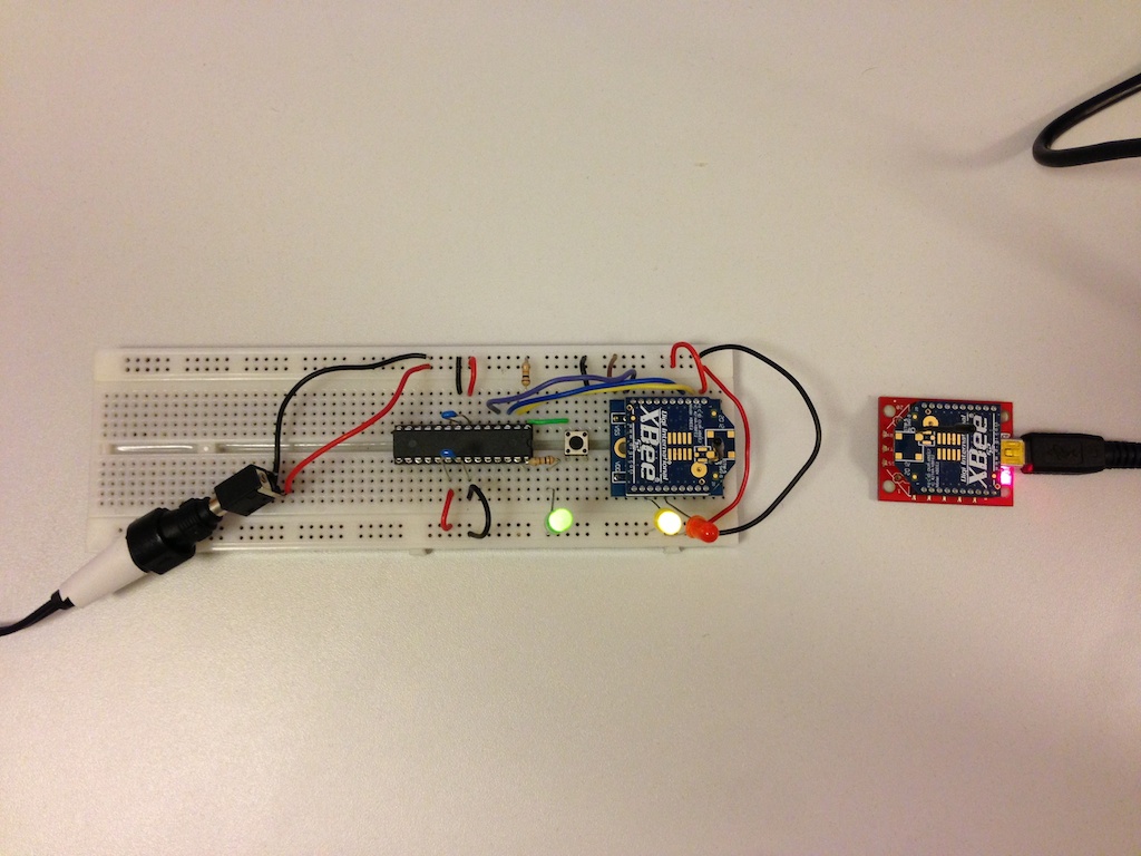
The circuit couldn’t be simpler: hook up 3.3V to an ATMEGA and an XBee and connect TX and RX from the ATMEGA to DOUT and DIN on the XBee. That’s it. This circuit also added two LEDs, connected directly to the XBee. These tell us a little about the status and connection of the XBee.
I’ve also connected the XBee’s DTR pin to port D2 (pin 4) on the ATMEGA. This will allow me to control the XBee’s status and put it to sleep. Adding a pushbutton to function as a reset button for the ATMEGA will also prove to be a valuable tool.
Software
The same software as with the MAX232 ↗ can literally be reused, but now without the wires.
Setup
When discussing the configuration we already covered setting up Zigbee nodes. For this first project, we select a coordinator in AT mode and a router in AT mode. The reason for not selecting an end-node right now, is to avoid issues with sleeping. A router never sleeps, which makes it easier to start of with.
The coordinator is hooked up to our computer using a USB explorer board and the router is hooked up to the ATMEGA as shown in the circuit above.
If we haven’t configured our nodes through the X-CTU tool, we can now do this through the AT admin/attention mode. To do so, we need to get the ATtention of our XBee. This can be don by pressing a sequence of three consecutive ‘+’ signs, without a return after it.
Once second later, the XBee will respond with OK. We now are no longer in transparent transmission mode and can give commands.
$ picocom --echo --imap crcrlf /dev/tty.usbserial-AD025LL3
picocom v1.7

port is        : /dev/tty.usbserial-AD025LL3
flowcontrol    : none
baudrate is    : 9600
parity is      : none
databits are   : 8
escape is      : C-a
local echo is  : yes
noinit is      : no
noreset is     : no
nolock is      : no
send_cmd is    : sz -vv
receive_cmd is : rz -vv
imap is        : crcrlf,
omap is        :
emap is        : crcrlf,delbs,

Terminal ready
+++OK
ATID
2222
Above the ATID command allows us to access the network ID. Without argument, the command retrieves the current value, with argument, it sets a new value.
With two more commands we can set the high and low parts of the address of the other party: ATDH and ATDL. The high part is the same for all XBees: 0013A200. The low part can be found on the bottom of the XBee.
As a final step, persist the new configuration using the ATWR command:
$ picocom --echo --imap crcrlf /dev/tty.usbserial-AD025LL3
...
Terminal ready
+++OK
ATID 2222
OK
ATDH 0013A200
OK
ATDL 40A2687E
OK
ATWR
OK
Action
Time to boot the ATMEGA, connect the coordinator using the USB explorer and fire up a terminal emulator…
$ picocom /dev/tty.usbserial-AD025LL3
picocom v1.7

port is        : /dev/tty.usbserial-AD025LL3
flowcontrol    : none
baudrate is    : 9600
parity is      : none
databits are   : 8
escape is      : C-a
local echo is  : no
noinit is      : no
noreset is     : no
nolock is      : no
send_cmd is    : sz -vv
receive_cmd is : rz -vv
imap is        :
omap is        :
emap is        : crcrlf,delbs,

Terminal ready
...
Nothing … whoops, that doesn’t seem to work. Let’s push the reset button and see what happens…
...
ATMEGA168 at your service...
shell> hello
       hello
shell> world
       world
shell> quit
       quit

session terminated.
Okay, what went wrong. It’s rather simple. When we first booted both the coordinator and the router, we could see that the router required a little time to associate itself with the network provided by the coordinator. All that time the orange LED was on. As soon as the router was associated, the orange LED started to flash.
But my old serial code didn’t wait until the XBees were associated and had already send it’s welcome message and was simply waiting for our input. When we pressed the reset button, the code on the ATMEGA started over, but now the XBees were associated and the transmission succeeded.
Pushing the Limits
So we’ve hit a first speed-bump. We need a way to wait at the ATMEGA side until the XBees are associated and connected, before starting to send out characters.
IF you dig through the documentation a bit, you will find the AI command, the Association Indicator. A value of 0x00 indicates that the node has successfully joined the network.
But, how to do this from the ATMEGA. We could implement the attention mode, wait 1 second, and so on. I’ve tried and failed - now YMMV, but I decided to move to the API mode at this point :-)
Other Limits
- Another obvious limit is that of the hard-coded destination address. In transparent mode, we only can chat with one other party.
- Of course, transparent mode doesn’t implement any communication protocol and would require us to implement some error checking and recovery.
- We also don’t get any feedback about what we transmit.
- And so on, and so on.
Cranking up the Possibilities
Time to solve al these limitation … enter API mode.
API mode allows us to construct packets in a standard format to do everything we couldn’t do in transparent mode and more. API mode allows us to transmit data to an addressable party, receive transmission reports, query the network for nodes and their parameters,… In short: everything and more.
Project 2: API
To improve on project 1, we would want to keep the same functionality, but with the ability to first wait for an association before we start sending out our header etc. We would basically want a wait_for_association call.
With project 2 I want to introduce another important aspect: power management. So besides the wait_for_assoiciation call, I also want a sleep and wakeup call to put the XBee in ultra-low power usage mode and bring it back up and running to send and receive data.
Configuration
The configuration of the nodes changes and new firmwares are needed: coordinator API and end-node API. Make sure, both have the same network ID, which now needs to be configured through X-CTU, because the node will no longer respond to +++.
Now, let’s correct that right away. All AT commands can be given in API mode also, but things are a bit more cryptic … or should I say hexy :-)
Talking HEX
Let’s introduce the API mode with an example: verifying the network ID. As you can see above, normally we would simple send the ATID command and get 4 hexadecimal digits back. Now, we need a little more.
Because I couldn’t find a quick way to send bytes using picocom or screen, I turned to python and wrote a little script:
import serial
import sys

ser = serial.Serial('/dev/tty.usbserial-AD025LL3', 9600)

# get hex from command line (skip first/script)
message = map(lambda a: int(a, 16), sys.argv[1:])

# take complement of last value/checksum
message[-1] = 0xff - message[-1]

# STEP 1: send string as hex
print 'send   : ', ' '.join('%02x'%i for i in message)
ser.write( bytearray(message) )

# STEP 2: print out the response packet

# wait for start of the frame
while(0x7e != ord(ser.read())): pass

# get length MSB (normally zero)
length_msb = ord(ser.read())
# get lenght LSB (normally the actual length)
length     = ord(ser.read())

# construct a response list
response = [ 0x7e, length_msb, length ]
for i in range(length+1):
   response.append(ord(ser.read()))

print 'receive: ', ' '.join('%02x'%i for i in response)
Okay, what’s happening here? The script takes a sequence of bytes from the command line. These bytes represent the payload of the packet we want to send. Next, the script receives a response packet and dumps it out on standard output.
So what would we be sending and what would we be receiving? A quick rundown of the Zigbee packet structure, using one simple example:
Every packet starts with 0x7e or 126 if you prefer integer notation ;-) Next, two bytes are used to represent the length of the packet, the former is the most significant byte, the latter the least. Often the former is simply 0x00 and the latter the one you want.
The length is calculated starting from the next byte: the frame type. In our example, we want to send an AT command, so we need to select frame type 0x08. The next byte is a frame ID, which is used in responses to correlate the response to the messages we send before. We need to specify this, because else, we don’t get any response. We take 0x01.
From this point on, the payload is frame type specific. An AT command consists of two bytes, representing the two letters, in our case ‘I’ and ‘D’ or 0x49 and 0x44.
The last byte is a checksum and it consists of the sum of the bytes taken into account for the length. Mind that this is an 8-bit number, so any higher bits are simply chopped of. In our case the sum is 0x96. If you look at the script, you see that it takes the complement, something I didn’t want to do manually in this case :-) I’ll probably change the script a bit to simply compute the entire checksum … maybe … some day.
So now we know what we are sending … what do we get back ?
$ python send.py 0x7e 0x00 0x04 0x08 0x01 0x49 0x44 0x96
send   :  7e 00 04 08 01 49 44 69
receive:  7e 00 0d 88 01 49 44 00 00 00 00 00 00 00 22 22 a5
The response bytes from left to right read: start of frame (0x7e), length (0x00 and 0x0d), AT response frame type (0x88), frame ID (0x01), a repetition of our command ‘ID’ (0x49 and 0x44), 8 bytes of data containing our answer (0x22 and 0x22) and finally a checksum (0xa5).
So the answer is 2222 which is what we expected.
Circuit
I’m using the same circuit as before, so no hardware changes here.
IMPORTANT
When we’re going to put nodes to sleep, it is important that their parent nodes, e.g. the coordinator, are aware of this. The XBee has a couple of settings (SN and SP) to configure their sleep period. For parents, this also means the time they expect their children to sleep … maximally. After this timeout they flush their associations with their children, causing them to re-associate again.
Make sure that parent nodes always have a setting for SP and SN that is equal or higher than the highest values of their children.
Software
On the software side, we need to implement some functions to handle the API. All code can be found in my XBee module at https://github.com/christophevg/embedded/blob/master/avr/xbee.c ↗.
A few highlights:
Send an AT command
void xbee_at(uint8_t ch1, uint8_t ch2, uint8_t id) {
  xbee_send_char(0x7E);   // start frame

  xbee_send_char(0x00);   // length MSB
  xbee_send_char(0x04);   // length LSB

  xbee_send_char(0x08);   // Frame type = AT
  xbee_send_char(id);     // Frame ID
  xbee_send_char(ch1);    // AT command char 1
  xbee_send_char(ch2);    // AT command char 2

  long sum = 0x08 + id + ch1 + ch2;
  xbee_send_char(0xFF - (sum & 0xFF) ); // checksum
}
This will look pretty familiar and implements the example detailed earlier, where we send an AT command.
Power Management
We also wanted power management in this project. Two xbee_ functions are implemented:
void xbee_sleep(void) {
  // power down XBee by setting its sleep pin high
  avr_set_bit(PORTD, XBEE_SLEEP);
}

void xbee_wakeup(void) {
  // power up XBee by setting its sleep pin low
  avr_clear_bit(PORTD, XBEE_SLEEP);
  xbee_wait_for_association();
}
Waiting for Association
void xbee_wait_for_association(void) {
  uint8_t value      = 0xFF;
  uint8_t id         = 0x00;

  while(value != 0) {
    _delay_ms(10); /* breath */
    id = id + 1;
    xbee_at('A', 'I', id);
    value = xbee_get_response(0x88, id, 'A', 'I');
  }
}