vCard
vCard
 Homemade by CVG
 My Homemade Apps
 Thingiverse
 Strava
MAX232
What do real programmers use to debug software ? Right, printf. And that’s what I also want to do from my ATMEGA168. So let’s add a serial interface to the board that allows us to use printf and have it displayed on our terminal window on our full fletched computer.
Introducing RS232
RS232 is the iconic name for the standard serial way of communicating. For years all computers were equipped with at least on RS232 port, even further back, it was all that was available.
One important aspect of RS232 is that both parties in the communication need to use the same speed. Further, RS232 requires a bit (or voltage peak) to be in the range of -12V to 12V.
It sounds all pretty old, but even today the basic RS232 remains probably the best interface for any system to report back to its user. Until further notice, I believe I will add it to any embedded design I’ll be making ;-)
The MAX232
To convert the -12V to 12V serial signal to one in the range of 0V to 5V, and vise versa, we can rely on an IC (originally) produced by Maxim, the MAX232. Integration is really easy and requires a few capacitors to allow the IC to bump the charge.
Although Maxim isn’t the only vendor anymore, offering this kind of IC, the name sticks, just like “a coke”.
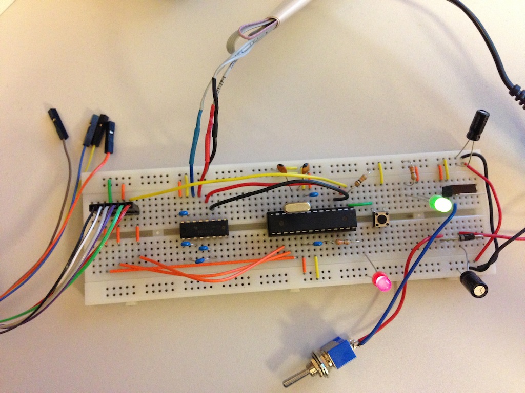
4 capacitors of 0.1μF, two uplinks to VCC and GND and two connections to the ATMEGA is all it takes to setup the hardware that allows the ATMEGA to communicate with the outside world.
Terminal Emulation
Before hooking up TX and RX to the ATMEGA, you can test the MAX232 by itself. With a wire, connect TX and RX and boot up a terminal session. This loop-back allows for easy testing of the RS232 part of the design.
Because my Mac doesn’t come with a serial port anymore, I bought a Digitus USB to serial adaptor ↗ some time ago. The drivers supplied by the vendor aren’t that up to date anymore, but luckily the use some other vendor’s hardware and so I found recent drivers ↗.
Terminal emulators are one of those whole wars. I tend to rely on screen.
$ screen /dev/tty.usbserial-FTSJ84AI 9600
hello world<ctrl+a><ctrl+k><y>
[screen is terminating]
The Code
After wiring RX to ATMEGA’s pin 2 (PD0/RXD) and TX to pin 3 (PD1/TXD), the circuit is ready to go. This is only the main part, for all details, refer to my Github embedded repository ↗.
// serial.c
// based on basic-in-atmega168.c from tutorial on Sparkfun

#include <stdio.h>
#include <avr/io.h>
#include <string.h>

#include "bool.h"
#include "bits.h"

#include "serial.h"

static FILE mystdout = FDEV_SETUP_STREAM(uart_putchar, NULL, _FDEV_SETUP_WRITE);

#define MAX_CMD_SIZE 64

#define STATUS_LED 0

int main(void) {
  bool    active = TRUE;
  uint8_t key = 0;

  char    buffer[MAX_CMD_SIZE+1];
  buffer[MAX_CMD_SIZE] = '\0';

  uint8_t index = 0;

  ioinit();

  printf("\n\nATMEGA168 at your service...\n");
  sbi(PORTC, STATUS_LED);

  while(active) {
    printf("shell> ");

    key   = 0;
    index = 0;
    while(key != 13 && index < MAX_CMD_SIZE) {
      key = uart_getchar();
      if(key == 13) {
        buffer[index] = '\0';
      } else {
        buffer[index] = key;
        printf("%c", key);  // echo
      }
      index++;
    }
    printf("\n       %s\n", buffer);
    active = strcmp(buffer, "quit\0"); // equal == 0 == FALSE ;-)
  }

  printf("\n\nsession terminated.\n");
  cbi(PORTC, STATUS_LED);

  return(0);
}

void ioinit(void) {
    // 1 = output, 0 = input
    DDRB = 0b11101111; // PB4 = MISO
    DDRC = 0b11111111; //
    DDRD = 0b11111110; // PORTD (RX on PD0)

    // USART Baud rate: 9600
    UBRR0H = MYUBRR >> 8;
    UBRR0L = MYUBRR;
    UCSR0B = (1<<RXEN0)|(1<<TXEN0);

    stdout = &mystdout; // required for printf init
}

static int uart_putchar(char c, FILE *stream) {
  if (c == '\n') uart_putchar('\r', stream); // add a CR before the LF

  loop_until_bit_is_set(UCSR0A, UDRE0);
  UDR0 = c;

  return 0;
}

uint8_t uart_getchar(void) {
  while( !(UCSR0A & (1<<RXC0)) );
  return(UDR0);
}
Compile and upload … (I’m using my cleaned up version of the previous Makefile here)
$ make clean program TARGET=serial
avr-gcc -c -mmcu=atmega168 -I. -DF_CPU=18000000UL -Os -funsigned-char -funsigned-bitfields -fpack-struct -fshort-enums -Wall -Wstrict-prototypes -Wa,-adhlns=serial.lst -std=gnu99 serial.c -o serial.o
avr-gcc -mmcu=atmega168 -I. -DF_CPU=18000000UL -Os -funsigned-char -funsigned-bitfields -fpack-struct -fshort-enums -Wall -Wstrict-prototypes -Wa,-adhlns=serial.o -std=gnu99 serial.o --output serial.elf -Wl,-Map=serial.map,--cref -lm
avr-objcopy -O ihex -R .eeprom serial.elf serial.hex
avr-objcopy -j .eeprom --set-section-flags=.eeprom="alloc,load" \
	--change-section-lma .eeprom=0 -O ihex serial.elf serial.eep
avr-objcopy: --change-section-lma .eeprom=0x0000000000000000 never used
avrdude -p atmega168 -P usb:5a:cb -c jtag2isp -U flash:w:serial.hex

avrdude: AVR device initialized and ready to accept instructions

Reading | ################################################## | 100% 0.15s

avrdude: Device signature = 0x1e9406
avrdude: NOTE: FLASH memory has been specified, an erase cycle will be performed
         To disable this feature, specify the -D option.
avrdude: erasing chip
avrdude: reading input file "serial.hex"
avrdude: input file serial.hex auto detected as Intel Hex
avrdude: writing flash (2158 bytes):

Writing | ################################################## | 100% 1.90s

avrdude: 2158 bytes of flash written
avrdude: verifying flash memory against serial.hex:
avrdude: load data flash data from input file serial.hex:
avrdude: input file serial.hex auto detected as Intel Hex
avrdude: input file serial.hex contains 2158 bytes
avrdude: reading on-chip flash data:

Reading | ################################################## | 100% 1.44s

avrdude: verifying ...
avrdude: 2158 bytes of flash verified

avrdude: safemode: Fuses OK

avrdude done.  Thank you.
Make sure you had a terminal emulation session ready to accept incoming information …
$ screen /dev/tty.usbserial-FTSJ84AI 9600
ATMEGA168 at your service...
shell> hello world
       hello world
shell> quit
       quit


session terminated.
Et voila, bi-direction communication …