vCard
vCard
 Homemade by CVG
 My Homemade Apps
 Thingiverse
 Strava
ATMEGA 168
The Atmel ATMEGA168 was the first MCU I programmed completely by myself, and it’s true what they say: when, after hours of fiddling and reviewing the circuit and every possible connection, the LED finally starts blinking, showing you’ve just programmed your first MCU, you feel so great. It’s really worth the pain.
The megaAVR 8-bit Family
The ATMEGA168 is a member of the megaAVR 8-bit family ↗. This means that it contains an 8-bit processor. It also contains 16 KB flash memory. Other family members are ATMEGA8 and the ATMEGA328, which all behave exactly the same, but carry different flash sizes.
The Programming Concept
To program (m)any MCU, we need to connect it to a programmer. This is a hardware part that allows a computer to interface with the MCU. There are typically a few ways to connect both: serial, ISP ↗ (In System Programming), JTAG ↗ (Joint Test Action Group),…
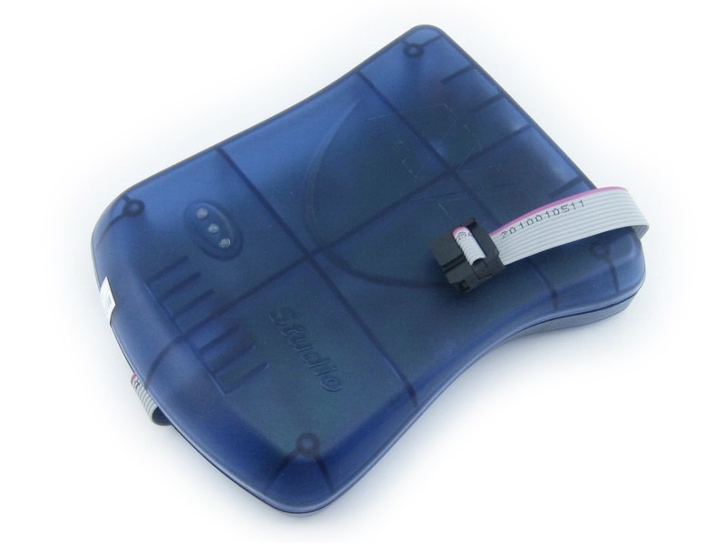
Which one to use depends on you MCU. In my case the ATMEGA168 supports ISP. I also own a JTAG ICE mkII, which supports ISP as a variant of the JTAG protocol.
ISP requires 6 connections to the MCU: for power VCC (5V) and GND (GrouND), for Input/Output MISO (Master In Slave Out, output) and MOSI (Master Out Slave In, input), control SCK (Serial ClocK) and RST (ReSeT).
ISP in fact connects the programmer to the MCU using SPI ↗ (Serial Peripheral Bus) - which makes it a bit confusing maybe. MISO, MOSI and SCK are the three wires that are used from the SPI, with the programmer being the master and the MCU being the slave. The power-related connections, along with the reset functionality allow the programmer to control the SPI communication.
The Programming Circuit
Although it basically boils down to connecting 6 wires to your MCU, we better add some more functionality and protection to smoothen the ride.
We start of with the regulated voltage power supply as the base for the programming circuit and prepare a ISP using SPI connection to our programmer (e.g. to the JTAGICE mkII.
Next we add the ATMEGA168. There are two parts to this: connecting the remaining SPI wires and powering the CMU.
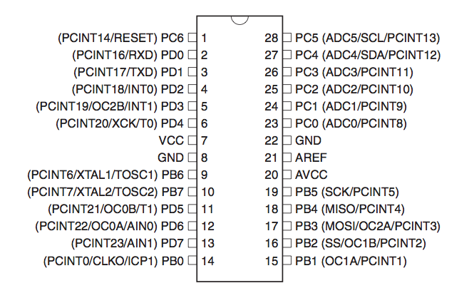
With SPI wired to the power supply, we now have to connect four more wires: MISO, MOSI, SCK and RST. To do this, we consult the MCU’s data sheet for the pin configuration.
The four pins we need to connect are pin 19 for SCK, pin 18 for MISO, pin 17 for MOSI and pin 1 for RESET. Connecting these pins would in fact be enough to continue and fire up the software to push the image through these pipes.
But a few additional wirings can make your life a lot better.
First we need to make sure that, even without the programmer connected, the MCU would get out of its reset state. The reset pin is an active low pin, meaning that without 5V connected to it, it will trigger the MCU’s reset functionality and the MCU will be constantly resetting and not doing anything.
So connecting it to a 5V source is enough. But is can be handy to have a switch to reset the MCU. So we extend the setup with a momentary switch, by default off, and of course a resistor to allow the current to flow from the 5V source to ground, thus bringing pin 1 low and active.
MCU programming requires a pretty stable 5V power supply. To ease out even more ripples the MCU’s VCC and GND connections are each bridged by a 0.1μF capacitor.
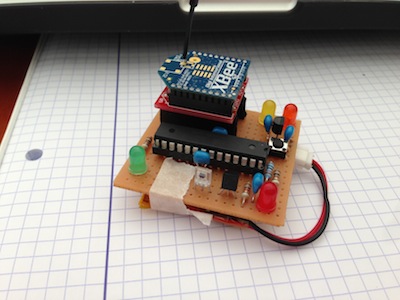
The final circuit on a breadboard looks something like this …
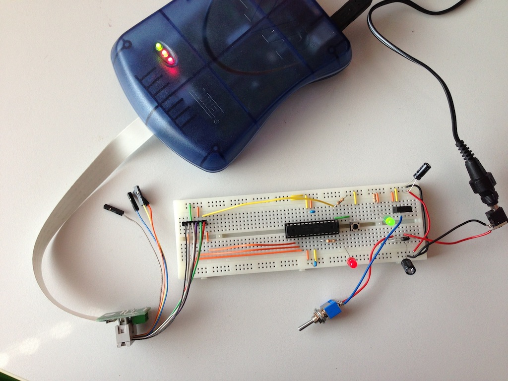
Mind that on the picture, an additional (red) LED is connected through a resistor to pin 23. This is one of the GPIO (General Purpose Input/Output) pins. The software we’re going to upload to the MCU in a minute will make this LED blink.
The Programming Process
Let’s create and upload the Hello World for embedded systems: make a LED blink.
Introducing blink.c
To not loose any time, I’m starting with the source code found at the wonderful tutorial on Sparkfun ↗. You can download a zip file with everything you need from their website ↗.
The source code is not too big and is interesting to take a look at. I also modified it a bit, because I wanted the blinking to be a bit more … complex ;-)
// blink.c
// based on blink_1MHz.c from tutorial on Sparkfun

#include <avr/io.h>

void ioinit(void);
void turn_ports_on(void);
void turn_ports_off(void);
void wait_ms(uint16_t x);

int main(void) {
    ioinit();

    while(1) {
      turn_ports_on();      wait_ms(500);
      turn_ports_off();     wait_ms(250);
      turn_ports_on();      wait_ms(500);
      turn_ports_off();     wait_ms(1000);
    }

    return(0);
}

void ioinit(void) {
    // 1 = output, 0 = input
    DDRB = 0b11111111; // all outputs
    DDRC = 0b11111111; // all outputs
    DDRD = 0b11111110; // PORTD (RX on PD0)
}

void turn_ports_on(void) {
  PORTC = 0xFF;
  PORTB = 0xFF;
  PORTD = 0xFF;
}

void turn_ports_off(void) {
  PORTC = 0x00;
  PORTB = 0x00;
  PORTD = 0x00;
}

void wait_ms(uint16_t x) {
  uint8_t y, z;
  for ( ; x > 0 ; x--){
    for ( y = 0 ; y < 90 ; y++){
      for ( z = 0 ; z < 6 ; z++){
        asm volatile ("nop"); // yikes, a busy loop ;-)
      }
    }
  }
}
Convert blink.c to blink.hex
First we need a compiler. This compiler isn’t your standard compiler maybe already available on your system. You need avr-gcc a Gnu C Compiler specially modified to produce AVR RISC binary images.
On my Mac this was … a breeze ;-)
$ port search avr-gcc
avr-gcc @4.7.2 (cross, devel)
    The GNU compiler collection for avr
$ sudo port install avr-gcc
...
--->  No broken files found.
Next we need to compile it. From the great tutorial on Sparkfun ↗, I happily reused their Makefile for now - until I have time to clean it up and extract what I need. For now, I edited it to reflect my setup with a a modified blink.c. Let’s make this…
$ make

-------- begin --------
avr-gcc (GCC) 4.7.2
Copyright (C) 2012 Free Software Foundation, Inc.
This is free software; see the source for copying conditions.  There is NO
warranty; not even for MERCHANTABILITY or FITNESS FOR A PARTICULAR PURPOSE.


Compiling: blink_1MHz.c
avr-gcc -c -mmcu=atmega168 -I. -gdwarf-2 -DF_CPU=8000000UL  -Os -funsigned-char -funsigned-bitfields -fpack-struct -fshort-enums -Wall -Wstrict-prototypes -Wa,-adhlns=blink_1MHz.lst  -std=gnu99 -MD -MP -MF .dep/blink_1MHz.o.d blink_1MHz.c -o blink_1MHz.o
blink_1MHz.c:13:20: fatal error: avr/io.h: No such file or directory
compilation terminated.
make: *** [blink_1MHz.o] Error 1
Whoops, we’re missing something ;-)
$ sudo port search avr-libc
avr-libc @1.8.0 (cross)
    C library for the AVR microcontroller.
astroboy:avr xtof$ sudo port install avr-libc
...
--->  No broken files found.
Let’s try that again …
$ make
-------- begin --------
avr-gcc (GCC) 4.7.2
Copyright (C) 2012 Free Software Foundation, Inc.
This is free software; see the source for copying conditions.  There is NO
warranty; not even for MERCHANTABILITY or FITNESS FOR A PARTICULAR PURPOSE.

Size before:
blink.elf  :
section          size      addr
.data               0   8388864
.text             246         0
.stab            1848         0
.stabstr          231         0
.comment           17         0
.debug_aranges     40         0
.debug_info       418         0
.debug_abbrev     221         0
.debug_line       186         0
.debug_frame      100         0
.debug_str        160         0
.debug_loc        132         0
.debug_ranges      24         0
Total            3623

Compiling: blink.c
avr-gcc -c -mmcu=atmega168 -I. -gdwarf-2 -DF_CPU=8000000UL  -Os -funsigned-char -funsigned-bitfields -fpack-struct -fshort-enums -Wall -Wstrict-prototypes -Wa,-adhlns=blink.lst  -std=gnu99 -MD -MP -MF .dep/blink.o.d blink.c -o blink.o

Linking: blink.elf
avr-gcc -mmcu=atmega168 -I. -gdwarf-2 -DF_CPU=8000000UL  -Os -funsigned-char -funsigned-bitfields -fpack-struct -fshort-enums -Wall -Wstrict-prototypes -Wa,-adhlns=blink.o  -std=gnu99 -MD -MP -MF .dep/blink.elf.d blink.o --output blink.elf -Wl,-Map=blink.map,--cref    -lm

Creating load file for Flash: blink.hex
avr-objcopy -O ihex -R .eeprom blink.elf blink.hex

Creating load file for EEPROM: blink.eep
avr-objcopy -j .eeprom --set-section-flags=.eeprom="alloc,load" \
	--change-section-lma .eeprom=0 -O ihex blink.elf blink.eep
avr-objcopy: --change-section-lma .eeprom=0x0000000000000000 never used

Creating Extended Listing: blink.lss
avr-objdump -h -S blink.elf > blink.lss

Creating Symbol Table: blink.sym
avr-nm -n blink.elf > blink.sym

Size after:
blink.elf  :
section          size      addr
.data               0   8388864
.text             246         0
.stab            1848         0
.stabstr          231         0
.comment           17         0
.debug_aranges     40         0
.debug_info       419         0
.debug_abbrev     223         0
.debug_line       186         0
.debug_frame      100         0
.debug_str        160         0
.debug_loc        132         0
.debug_ranges      24         0
Total            3626
-------- end --------
Much better.
Uploading blink.hex
Now we have our blink.hex image, we want to upload it to the MCU’s flash memory and have it run.
You can use the make program target, but using avrdude is not that hard and I think it’s better to keep this well under control
avrdude -p atmega168 -P usb:5a:cb -c jtag2isp    -U flash:w:blink.hex

avrdude: AVR device initialized and ready to accept instructions

Reading | ################################################## | 100% 0.15s

avrdude: Device signature = 0x1e9406
avrdude: NOTE: FLASH memory has been specified, an erase cycle will be performed
         To disable this feature, specify the -D option.
avrdude: erasing chip
avrdude: reading input file "blink_1MHz.hex"
avrdude: input file blink_1MHz.hex auto detected as Intel Hex
avrdude: writing flash (208 bytes):

Writing | ################################################## | 100% 0.26s

avrdude: 208 bytes of flash written
avrdude: verifying flash memory against blink_1MHz.hex:
avrdude: load data flash data from input file blink_1MHz.hex:
avrdude: input file blink_1MHz.hex auto detected as Intel Hex
avrdude: input file blink_1MHz.hex contains 208 bytes
avrdude: reading on-chip flash data:

Reading | ################################################## | 100% 0.16s

avrdude: verifying ...
avrdude: verification error, first mismatch at byte 0x0000
         0x0c != 0x00
avrdude: verification error; content mismatch

avrdude: safemode: lfuse changed! Was c2, and is now fe
Would you like this fuse to be changed back? [y/n]
Holy crap, why doesn’t this work ? …
About fuses
Because you don’t know what link in the chain is failing, you have to go through everything, over and over again. At this point I wasn’t even sure if I could trust the sources I was using, etc.
After a while, digging through Google results, I was introduced to fuses, as they could be a cause for my problems. It was possible that a bit in the high fuse wasn’t set, resulting in a disabled SPI. Which means I wouldn’t be able to program my MCU.
After getting more and more familiar with avrdude, I learned how to read out the fuse bytes. I had two MCU’s: an old one from a kit I bought @ HAR2009 and a brand new one, I bought 24 hours earlier, just to be sure I had one working.
Their high fuse bytes were respectively: DD and DF. Translating this to a bit-string representation gives 1101 1101 and 1101 1111. We need to read these bit-strings from right to left, starting with index 0. The fifth bit then indicates whether SPI is enabled. In our case this is the third bit from the right, a zero. No worries, zero is a good thing here, it means that SPI is enabled.
At this point I knew that I should be able to access the MCU using SPI, so I should also be able to burn the fuses. I looked up the defaults, hoping this might reset some other settings that might be faulty.
I used the default fuse settings found on the Embedded AVR Fuse Calculator ↗. According to this source, the high fuse byte should be DF, the low fuse byte should be 62 and tried to burn these to the MCU.
$ avrdude -p atmega168 -P usb:5a:cb -c jtag2isp -U lfuse:w:0x62:m -U hfuse:w:0xdf:m -U efuse:w:0xf9:m

avrdude: AVR device initialized and ready to accept instructions

Reading | ################################################## | 100% 0.15s

avrdude: Device signature = 0x1e9406
avrdude: reading input file "0x62"
avrdude: writing lfuse (1 bytes):

Writing | ################################################## | 100% 0.05s

avrdude: 1 bytes of lfuse written
avrdude: verifying lfuse memory against 0x62:
avrdude: load data lfuse data from input file 0x62:
avrdude: input file 0x62 contains 1 bytes
avrdude: reading on-chip lfuse data:

Reading | ################################################## | 100% 0.05s

avrdude: verifying ...
avrdude: 1 bytes of lfuse verified
avrdude: reading input file "0xdf"
avrdude: writing hfuse (1 bytes):

Writing | ################################################## | 100% 0.05s

avrdude: 1 bytes of hfuse written
avrdude: verifying hfuse memory against 0xdf:
avrdude: load data hfuse data from input file 0xdf:
avrdude: input file 0xdf contains 1 bytes
avrdude: reading on-chip hfuse data:

Reading | ################################################## | 100% 0.05s

avrdude: verifying ...
avrdude: 1 bytes of hfuse verified
avrdude: reading input file "0xf9"
avrdude: writing efuse (1 bytes):

Writing |                                                    | 0% 0.00s ***failed;
Writing | ################################################## | 100% 0.40s

avrdude: 1 bytes of efuse written
avrdude: verifying efuse memory against 0xf9:
avrdude: load data efuse data from input file 0xf9:
avrdude: input file 0xf9 contains 1 bytes
avrdude: reading on-chip efuse data:

Reading | ################################################## | 100% 0.05s

avrdude: verifying ...
avrdude: verification error, first mismatch at byte 0x0000
         0xf9 != 0x01
avrdude: verification error; content mismatch

avrdude: safemode: efuse changed! Was f9, and is now 1
Would you like this fuse to be changed back? [y/n] n
avrdude: safemode: Fuses OK

avrdude done.  Thank you.
It seemed that I could burn the high and low fuse, but not the extended. I tried it some more times, but the result stayed the same. For some reason, I tried to upload the image …
One more time …
$ avrdude -p atmega168 -P usb:5a:cb -c jtag2isp -U flash:w:blink.hex

avrdude: AVR device initialized and ready to accept instructions

Reading | ################################################## | 100% 0.15s

avrdude: Device signature = 0x1e9406
avrdude: NOTE: FLASH memory has been specified, an erase cycle will be performed
         To disable this feature, specify the -D option.
avrdude: erasing chip
avrdude: reading input file "blink.hex"
avrdude: input file blink.hex auto detected as Intel Hex
avrdude: writing flash (244 bytes):

Writing | ################################################## | 100% 0.31s

avrdude: 244 bytes of flash written
avrdude: verifying flash memory against blink.hex:
avrdude: load data flash data from input file blink.hex:
avrdude: input file blink.hex auto detected as Intel Hex
avrdude: input file blink.hex contains 244 bytes
avrdude: reading on-chip flash data:

Reading | ################################################## | 100% 0.21s

avrdude: verifying ...
avrdude: 244 bytes of flash verified

avrdude: safemode: Fuses OK

avrdude done.  Thank you.
It worked. Apparantly there actually was something wrong with the fuses and after resetting them to their default values (at least the high and low fuse bytes), the upload process did work.
And yes … the red LED was blinking
Understanding the fuses problem
With a working setup, I first wanted to get this documented. That has been done now :-) The next step is to understand what was wrong. What setting in the fuses prohibited me from uploading my image.
Coming soon … (I hope)
The Need for Speed
The ATMEGA168 by default is configured to use its internal oscillator, which operates at 1Mhz (kind of). The ATMEGA168 supports up to 20MHz, which allows it to process 20 MIPS (Million Instructions Per Second).
8MHz
By default, the ATMEGA168 does run at 1MHz, but this achieved by a fuse setting, dividing the speed by 8. If we look at the definition of the low fuse byte (by default 0x62 or 0110 0010), we see that the 7th bit (the left-most one) is 0, which means that it’s programmed. The definition describes this bit as name: CKDIV8(4), bit: 7, description: Divide clock by 8, default: 0 (programmed). So is we change it to 1, the low byte fuse needs to be 1110 0010 or 0xE2.
$ avrdude -p atmega168 -P usb:5a:cb -c jtag2isp -U lfuse:w:0xE2:m

avrdude: AVR device initialized and ready to accept instructions

Reading | ################################################## | 100% 0.15s

avrdude: Device signature = 0x1e9406
avrdude: reading input file "0xE2"
avrdude: writing lfuse (1 bytes):

Writing | ################################################## | 100% 0.15s

avrdude: 1 bytes of lfuse written
avrdude: verifying lfuse memory against 0xE2:
avrdude: load data lfuse data from input file 0xE2:
avrdude: input file 0xE2 contains 1 bytes
avrdude: reading on-chip lfuse data:

Reading | ################################################## | 100% 0.05s

avrdude: verifying ...
avrdude: 1 bytes of lfuse verified

avrdude: safemode: Fuses OK

avrdude done.  Thank you.
And immediately our red LED is blinking 8 times faster.
This also shows that we need to take this into account when programming, especially when dealing with timings. Remember the wait_ms() function?
void wait_ms(uint16_t x) {
  uint8_t y, z;
  for ( ; x > 0 ; x--){
    for ( y = 0 ; y < 90 ; y++){
      for ( z = 0 ; z < 6 ; z++){
        asm volatile ("nop"); // yikes, a busy loop ;-)
      }
    }
  }
}
This is now no longer calibrated to the speed of our MCU. And if we want to write portable code, we even don’t want to bother. The Sparkfun Makefile implements a way to abstract this.
# Processor frequency.
#     This will define a symbol, F_CPU, in all source code files equal to the
#     processor frequency. You can then use this symbol in your source code to
#     calculate timings. Do NOT tack on a 'UL' at the end, this will be done
#     automatically to create a 32-bit value in your source code.
F_CPU = 8000000
But the blink code isn’t using this feature. It turns out that the AVR LibC library has its own support through _delay_ms() from util/delay.h, which takes into account F_CPU and allows us to clean up the code further and make it CPU frequency invariant.
// blink.c
// based on blink_1MHz.c from tutorial on Sparkfun

#include <avr/io.h>
#include <util/delay.h>

void ioinit(void);
void turn_ports_on(void);
void turn_ports_off(void);

int main(void) {
    ioinit();

    while(1) {
      turn_ports_on();   _delay_ms(500);
      turn_ports_off();  _delay_ms(250);
      turn_ports_on();   _delay_ms(500);
      turn_ports_off();  _delay_ms(1000);
    }

    return(0);
}

void ioinit(void) {
  // 1 = output, 0 = input
  DDRB = 0b11111111; // all outputs
  DDRC = 0b11111111; // all outputs
  DDRD = 0b11111110; // PORTD (RX on PD0)
}

void turn_ports_on(void) {
  PORTC = 0xFF;
  PORTB = 0xFF;
  PORTD = 0xFF;
}

void turn_ports_off(void) {
  PORTC = 0x00;
  PORTB = 0x00;
  PORTD = 0x00;
}18MHz
That’s the fastest the MCU can go without external help. But, adding an external oscillating crystal is easy. It needs to be connected to pins 9 and
- To make sure that the crystal starts oscillating, we need to add two 22pF capacitors before connecting the crystal to GND.
But that’s not all. The MCU also needs to be configured to use this external crystal. For an external full swing crystal oscillator we need 4 first bits (the right-most or CKSEL3..0) to be set to 0111 or 0110.
The first (right-most) bit, as well as the 3 of the 4 remaining bits depend on the way the oscillator behaves at start-up. Based on what I can read I think I have to go for Crystal Oscillator, slowly rising power, which requires SUT1..0 = 11 and CKSEL0 = 1, resulting in 1111 0111 or 0xF7.
Fingers crossed …
$ avrdude -p atmega168 -P usb:5a:cb -c jtag2isp -U lfuse:w:0xF7:m

avrdude: AVR device initialized and ready to accept instructions

Reading | ################################################## | 100% 0.15s

avrdude: Device signature = 0x1e9406
avrdude: reading input file "0xF7"
avrdude: writing lfuse (1 bytes):

Writing | ################################################## | 100% 0.15s

avrdude: 1 bytes of lfuse written
avrdude: verifying lfuse memory against 0xF7:
avrdude: load data lfuse data from input file 0xF7:
avrdude: input file 0xF7 contains 1 bytes
avrdude: reading on-chip lfuse data:

Reading | ################################################## | 100% 0.05s

avrdude: verifying ...
avrdude: 1 bytes of lfuse verified

avrdude: safemode: Fuses OK

avrdude done.  Thank you.
The LED is blinking like crazy, of course we need to adjust the CPU frequency parameter in the Makefile, rebuild and upload.
And then the LED is blinking again at the expected rates, while the CPU is running at 18MHz.