vCard
vCard
 Homemade by CVG
 My Homemade Apps
 Thingiverse
 Strava
JTAGICE mkII
There are many programmers, but because I know I’ll also will need to debug stuff on my MCU’s, I decided to buy the more advanced JTAGICE mkII.
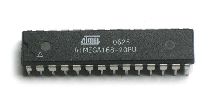
To handle the programmer when programming e.g. my ATMEGA168, I use avrdude.
ISP using SPI
The JTAGICE mkII comes with the squid cable, a female JTAG connector with 10 loose wires. It allows you to separate the 6 wires needed to connect the ISP ↗ (In System Programmer) to the MCU’s SPI ↗. The following table shows which 6 of the 10 JTAG wires are matched to the wires from the squid cable:
| JTAG pin no. | JTAG pin desc. | MCU pin desc. | Squid Cable Color |
|---|---|---|---|
| 1 | TCK | SCK | black |
| 2 | GND | GND | white |
| 3 | TDO | MISO | grey |
| 4 | VTref | VTref(=VCC) | purple |
| 5 | |||
| 6 | nSRST | RESET | green |
| 7 | |||
| 8 | |||
| 9 | TDI | MOSI | red |
| 10 |
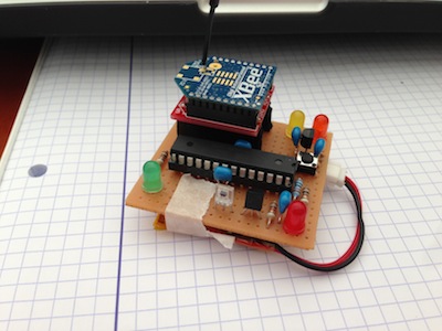
When setting this up on a breadboard, I use 6 pins of a break-away 0.1” strip male header. This allows me to cleanly connect the 6 required wires. If I want to add this to a PCB, I can of course use a 10 (5x2) pin female connector into which the JTAG connector can be plugged in.

Two wires can already be connected to their final destination: VTref and GND can go respectively to the 5V (regulated) power supply and GND to ground. The four remaining wires will need to be connected to the MCU that is going to be programmed or debugged.
- Connecting to a target board with the AVR JTAGICE mkII ↗
- JTAGICE mkII Hardware Description ↗
- Connecting to an SPI target ↗
JTAG
After the ATMEGA168, I started using the ATMEGA1284p. This MCU comes with a lot more memory, two USARTs,… but also with a JTAG interface.
You live you learn … For some reason I initially thought that the JTAG protocol was only for debugging, so I used ISP using SPI as describeb above to program and JTAG for debugging, requiring me to switch back and forth between ISP and JTAG. I wondered if I couldn’t program using JTAG. Short story: of course, it simply works :-)
The setup isn’t that different from the ISP setup. The programming process using avrdude remains identical, apart from the the -c switch that now simple is set to jtag2.
$ avrdude -p atmega1284p -P usb:5a:cb -c jtag2 -U flash:w:main.hex

avrdude: AVR device initialized and ready to accept instructions

Reading | ################################################## | 100% 0.00s

avrdude: Device signature = 0x1e9705
avrdude: NOTE: FLASH memory has been specified, an erase cycle will be performed
         To disable this feature, specify the -D option.
avrdude: erasing chip
avrdude: reading input file "main.hex"
avrdude: input file main.hex auto detected as Intel Hex
avrdude: writing flash (1930 bytes):

Writing | ################################################## | 100% 0.13s

avrdude: 1930 bytes of flash written
avrdude: verifying flash memory against main.hex:
avrdude: load data flash data from input file main.hex:
avrdude: input file main.hex auto detected as Intel Hex
avrdude: input file main.hex contains 1930 bytes
avrdude: reading on-chip flash data:

Reading | ################################################## | 100% 0.16s

avrdude: verifying ...
avrdude: 1930 bytes of flash verified

avrdude: safemode: Fuses OK

avrdude done.  Thank you.