vCard
vCard
 Homemade by CVG
 My Homemade Apps
 Thingiverse
 Strava
Regulated Voltage Circuit
This page is more than 10 years old and besides the fact that the circuit diagrams are no longer available, it needs some love. I intent to clean it up in the near future, so keep posted…
The wall socket in your house gives you 110 to 240V, depending on your physical location in the world. Embedded systems typically use much lower voltages. Also the current you get from the wall socket is typically AC (Alternating Current). Embedded systems typically use DC (Direct Current). They are also much more susceptible to glitches in their power supply.
Therefore it is important to have a very stable power supply to hook up your designs. There are basically two ways to get your systems powered: batteries and via an adapter, connected to the electric grid.
The 5V Circuit
The circuit below shows somewhat the default circuit you’ll set up when designing something around a processor (of course one requiring 5V).
It consists of a 9V source, typically from an adapter plugged into the an electric wall socket which is routed through an LM7805 regulator. This regulator will bring down the voltage to 5V and try to ease out the ripples in the voltage.
By itself, this could be considered enough, but the regulator is not perfect. The circuit provides some extras: first of all a diode (D0) is added to avoid wrongly oriented currents, causing havoc on our circuits. Next comes a switch to more easily control the status of the design. At the end we also add a LED (protected by a resistor), simply to have a visual indication that everything is ok.
These are all additions to make our lives easier and are not mandatory. The two capacitors on the other hand are, although also not required, a good thing to add to the design. They each bridge one side of the circuit, a 100 μF on the 9V side and a 10 μF on the 5V side. When all goes well, they charge until full and then when ripples occur and the voltage drops, they kick in and discharge, easing out the ripples even further.
Laying things out on a breadboard and adding a switch …
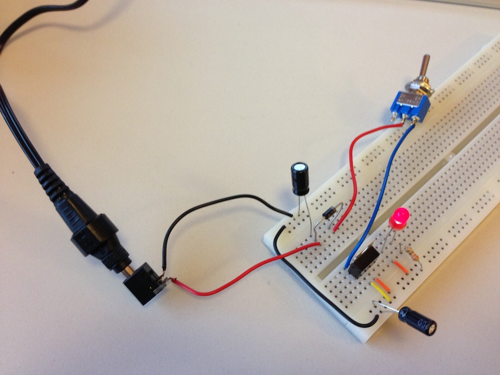
To avoid dismantling the connector on the adapter, I’ve added a barrel jack. This allows me to simply plug in the connector from the adapter.
The 3V Circuit
While designing my first mote, I wanted to use a LIPO battery of 3.7V with 1400mAh ↗. My design required 3.3V, so I had to create a drop. With a little help from a friend ↗, I found the MCP1700 ↗, which perfectly fitted my requirements.