vCard
vCard
 Homemade by CVG
 My Homemade Apps
 Thingiverse
 Strava
Electronics - first steps
This page is more than 10 years old and besides the fact that the circuit diagrams are no longer available, it needs some love. I intent to clean it up in the near future, so keep posted…
While doing research for possible master thesis topics, I’m looking into the idea of wireless sensor network. At KULeuven the DISTRINET research group is spending quiet some effort into this and I want to make sure that I fully understand it before I decide to move in this direction or not.
One part is wireless sensor networks, which I’m looking into using the Raven boards. Another part consists of designing and implementing an electronics component.
This page is kind of a transcript of my first steps into electronics, which will hopefully end with a working prototype of the component I need to develop if I take on that thesis topic.
Step 1 : Let’s start reading
I really thought that it would take a Google search and potentially some bucks to buy the de facto introduction reading material and be on my way.
That turned out not to be the case. So I was probably looking in the wrong places, not using the right keywords. A few months back I attended a soldering class by Mitch Altman. I tried consulting him for any good references, but with no luck. He even pointed out that he also didn’t know of any good books to get started and that he might be releasing one in a not so distant future.
It seems that, in contrast to the (desktop/server) software worls where I come from, the electronics world is not that novice-friendly documented (yet). One of the problems probably is also that it contains such a broad spectrum of possibilities, that there isn’t one (right) way to introduce someone to electronics. This means that I also will have to digg in and start reading until some pieces start falling into place.
On the wonderful StackOverflow scene I found a page dealing with my exact question, titled: Basic Electronics Book ↗. It lists some great books, but all of them are mainly references. From experience I know that at this embryonic stage, one needs a book that is a bit easier to read and reads more like a story with a specific point of view.
After some more searches I (once again) ended up at O’Reilly’s.
Book 1 : Making Embedded Systems
The first book I took on was “Making Embedded Systems ↗”. I think it was the right book to get me started from the world I came from, looking at embedded systems from a software developer’s point of view, while introducing the hardware concepts pretty good.
Although it is nowhere near the component I will need to design and implement, I soon realized that I was required to go through the entire chain of Hello World steps all over again. Only this time Hello World means playing with blinking LEDs.
And although this book does indeed introduce many hardware aspects pretty nicely, it also points out that it barely scratches the surface and therefore refers to another (sister-) book “Designing Embedded Hardware ↗”, one that I also already had found through other searches.
Book 2 : Designing Embedded Hardware
After a great introduction, picking up this book was a great experience. Still very much an introduction with many pointers to more, but once more a step up the learning curve.
Its focus is a lot more on hardware and that was the right next step. Finally I was introduced to SPI and other important aspects.
Book 3 : Make: Electronics
I hesitated a long time before actually buying it, but this is really a great book when trying to pickup electronics in a hands-on fashion. Many of the initial experiments below where constructed from examples from this book.
Diagrams
To document circuits on my online pages I used Circuits.io. Over the years it has been acquired by Autodesk and transformed, dropping the support for rendering simple circuits. I’ll be redoing all circuits in the near future.
Hardware
There are many sources to consult with respect to getting an initial hardware setup. Below is a rough list of the hardware I bought during the first months.
- Digital Multi-meter: UNI-T UT39B
- soldering iron: Weller SPI-27 25W
- solder Sn60Pb40 - 0.80mm and 0.60mm
- helping hand
- pointy wirecutter
- 2 breadboards
- 3 PCB boards
- battery packs for 2 and 4 AA batteries
- assorted resistors & condensators pack from Vellman
- most of the components from the shopping lists from the Make: Electronics book
- solid wires in various colours
- …
Step 2 : Hello World
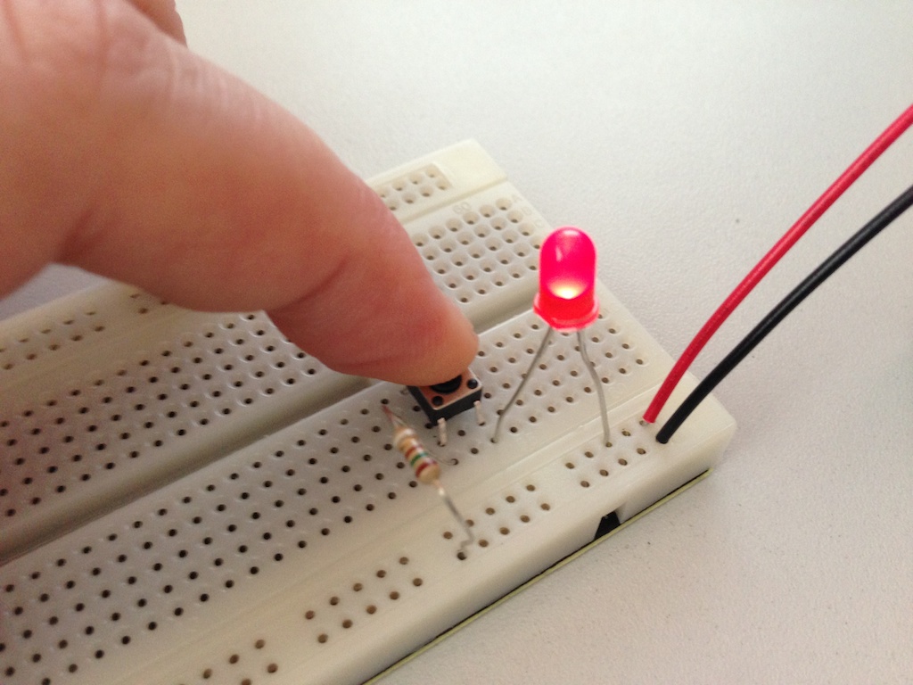
Although I’d love to create something that my wife doesn’t frown upon, I have to start with the basics: make a LED light up … without burning it.
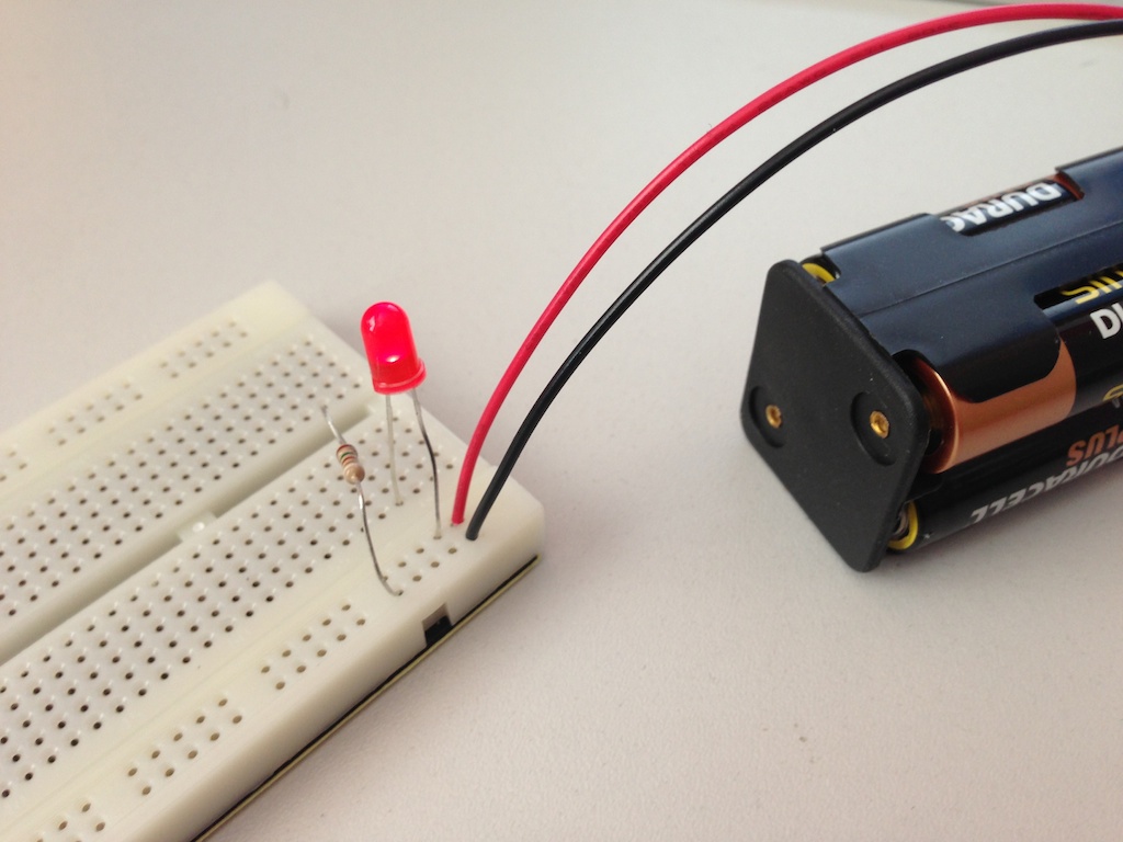
It’s of course a bit more practical with a button :-)
Next up of course is having the LED fade in and out, like a heart-beat. I followed the different examples from the excellent Make: Electronics book here.
First a basic setup with a relay. A relay basically contains a coil and a 2-way switch. When current flows through the coil, it magnetizes and it will push the switch into the other position. When well connected, this might also cause it to be no longer powered, thus losing its magnetic property and the swith will fall back into its original position. And the cycle repeats itself.
The circuit is not that difficult, although that it looks a bit more complicated at first. Just start at the power source and follow the current. Notice that I’ve created a setup with two battery sources: one 9V and one consisting of two 1.5V AA batteries. Combined in series these result in a power source of 12V (9 + 2x1.5).
A relay looks kind of bulky, so let’s introduce the transistor. Just like a relay, it can switch a flow of electricity. It has three pins: the collector, base and emitter. The collector receives current, the base controls the flow and the emitter sends it through.
You could compare it to a switch: If you put a little current on the base, the switch is closed and the current flows from the collector to the emitter. So it’s basically a on/off switch. In the case of the relay, we have a two-way on switch. To create the same effect, two transistors, turning each other on and of are needed.
Note: In the movie I’ve added a switch, which is not included in the diagram :-)
But it’s not quiet yet the effect I’m aiming for. Let’s try it with the famous 555 timer.
Yeah, we made heart beat ;-)
The 555 timer hides (a lot of) the complexity. Let’s see if I can explain everything in the diagram:
- connecting GND (pin 1) and VCC (pin 8) are pretty straightforward
- RESET requires a high value to avoid resetting (it’s active low), so connected to the power source, it will keep the timer running.
That leaves us with TRIG (pin 2), OUT (pin 3) and THRES (pin 6).
The 555 timer allows us to generate a “pulse”. This happens when the voltage on the TRIGger is low (another active low). Internally, the timer will flip into a different state.
The pulse is a fixed-time high voltage on OUT. The length of the pulse is determined by the capacitance of the capcitor connected on TRESH (pin 6). When this charges to 2/3, TRESH will detect this and internally, the timer will flop back.
So let’s walk through the circuit: initially there is no high voltage on TRIG, which triggers the flip and 9V is put on OUT. This causes capacitor C0 to start charging, causing an increasing voltage on the transistor, which will start eluminating the LED. After 2/3 of its charging time, TRESH will cause a flop and OUT goes back to low voltage.
Capacitor C0 now starts to discharge, causing a high voltage on TRIG for some time. When C0 is fully discharged, the cycle repeats itself.
Okay, I understand the circuit. Now I want to modify it and actually show the discharging of capacitor C0 back to OUT (which internally sinks this to GND).
This current will flow back through resistor R1, so I can put a LED in parallel to that. To only show the back-current when discharging the capacitor, I added a diode to that branch, blocking any charge current from going through the LED.
Although this works, it doesn’t seem to be a classic setup. It would be nice if the output was taken out of the loop generation and only be used to do something (else).
Also, the 555 can be configured (programmed is a bit strong here I think). The length of the pulse (or the duration of the “on” cycle) and the length of the interval (or the duration of the “off” cycle) can be set using resistors.
Let’s once more walk through the entire circuit to make sure we get how it works. When activating the power source, the current flows through R1 and the 200K trimmer. It starts to charge capacitor C0, thus keeping the voltage on TRIG initially low, which activates it and a high voltage on OUT will make the LED
When C0 reaches 2/3 of its capacity, THRES will be activated which causes OUT to go low. When the 555 flops back, DISCH will be grounded and allow for sinking. This allows for C0 to discharge, until it reaches a level that again triggers TRIG and the cycle repeats.
The 200K trimmer allows us to control the rate at which the capacitor charges and discharges, thus allowing us to control the frequency of the oscillation. There is in fact a little difference between charging and discharging. When charging, the current flow through both R1 and the 200K trimmer and while discharging only through the trimmer.
This can be eliminated by adding a diode in parallel with the trimmer, which will eliminate it from the charge cycle and only include it in the discharge cycle. This way the charge and discharge cycles can be configured independently.
The CONT pin can be used to configure the timing/sensitivity of the RC circuit. It seems that it is not often used, but varying the voltage will change the speed.
Step 3 : Play
Once you get the hang of it, it is more of the same. Not that it becomes boring, on the contrary, but you can start having fun trying out thing. Below is a list of other small pages that deal with different experiments.