 vCard
vCard
 Homemade by CVG
 My Homemade Apps
 Thingiverse
 Strava
EZRPi
The EZRPi is a Raspberry Pi HAT ↗, carrying a Silicon Labs EZR32 ↗ Sub-GHz wireless microcontroller (MCU), that adds subGHz radio capabilities to the RPi.
Different protocols can be implemented on the MCU, ranging from basic physical-layer-only ad-hoc communication to full-stack networking protocols. An example of such protocol is Dash-7. Dash7 is a specification for an ultra low power network stack, operating within the sub-GHz spectrum. The Dash7 Open Source Stack (OSS-7) ↗ can be flashed onto the EZR to turn it into a modem, accessible from the Raspberry Pi. On the Pi, one then could talk to this modem using pyd7a ↗ a collection of Python modules, supporting the DASH7 Alliance Protocol in general, and OSS-7 in particular..
While my GitHub repository ↗ contains all design and implementation source files of this generic sub-GHz Raspberry Pi HAT, on this page, I’m collecting overview & background information on the project, links to useful resources, remarks, wishes, angry screams,…
Rationale
Having been working in the IoT space for almost three years now and being in love with creating new embedded devices for about two more years, I’ve already witnessed an incredible evolution. Every thing is becoming connected, making the WiFi space more and more crowded.
At certain locations the amount of wireless communication in the gigahertz range causes the network to become unreliable and even unusable for critical applications. People are looking at different solutions to get around this rising issue, looking for new backbones for the ever increasing need for wireless communication.
As I’ve learned over the past years, the sub-GHz range of wireless communication might be a solution. While “classic” usage wants faster networks, for which people are looking at e,g, 5GHz, and beyond - 24GHz anyone? 60? - a great deal of applications don’t require the vast amounts of data to be transmitted and rather require small amounts of data to be communicated. Certainly in the IoT space, where the users are small devices with hardly video-streaming or other heavy downloading needs, looking at a slower, but possibly more reliable network might be a good solution to overcome the over-crowding of the human space.
Sub-GHz network protocols, like Dash7, Z-Wave, SigFox, LoRaWAN,… offer lower data rates, but offer much longer range communication at a much lower energy cost. So besides not competing for space in the 2.4 or 5 GHz frequency range, they come with additional bonus value.
Currently several break-out boards are popping up on the market, offering access to many of the mentioned networks. Still in its infancy, they all come with pros and cons, but most of the time all require an environment specific to their implementation in one way or the other. And although developing a network stack is surely not for the faint-of-heart, the underlying basics are doable even for enthousiasts.
The EZR32 by Silicon Labs is a microcontroller with a sub-GHz transceiver in a single package. It has everything on board to start talking and listening in this sub-GHz space.
With this project I want to create a generic solution to bring the sub-GHz range to Raspberry Pi, without focussing on one specific network stack.
With the EZR32 operating as a modem to the Raspberry Pi, the complexity of the network stack can be hidden on the EZR, while using the network can be as simple as send "hello world" or listen on 100.9MHz.
Although this project is indifferent about network-technology, two demo implementations will be provided: the Dash7 Open Source Stack provides out-of-the box functionality to make the EZR32 operate as a modem, accessible through an AT-command set.
On the other hand, I want to implement a minimal and ultra-basic network “stack” to illustrate what is really needed to be able to make devices talk.
We’ll see where this leads me :-)
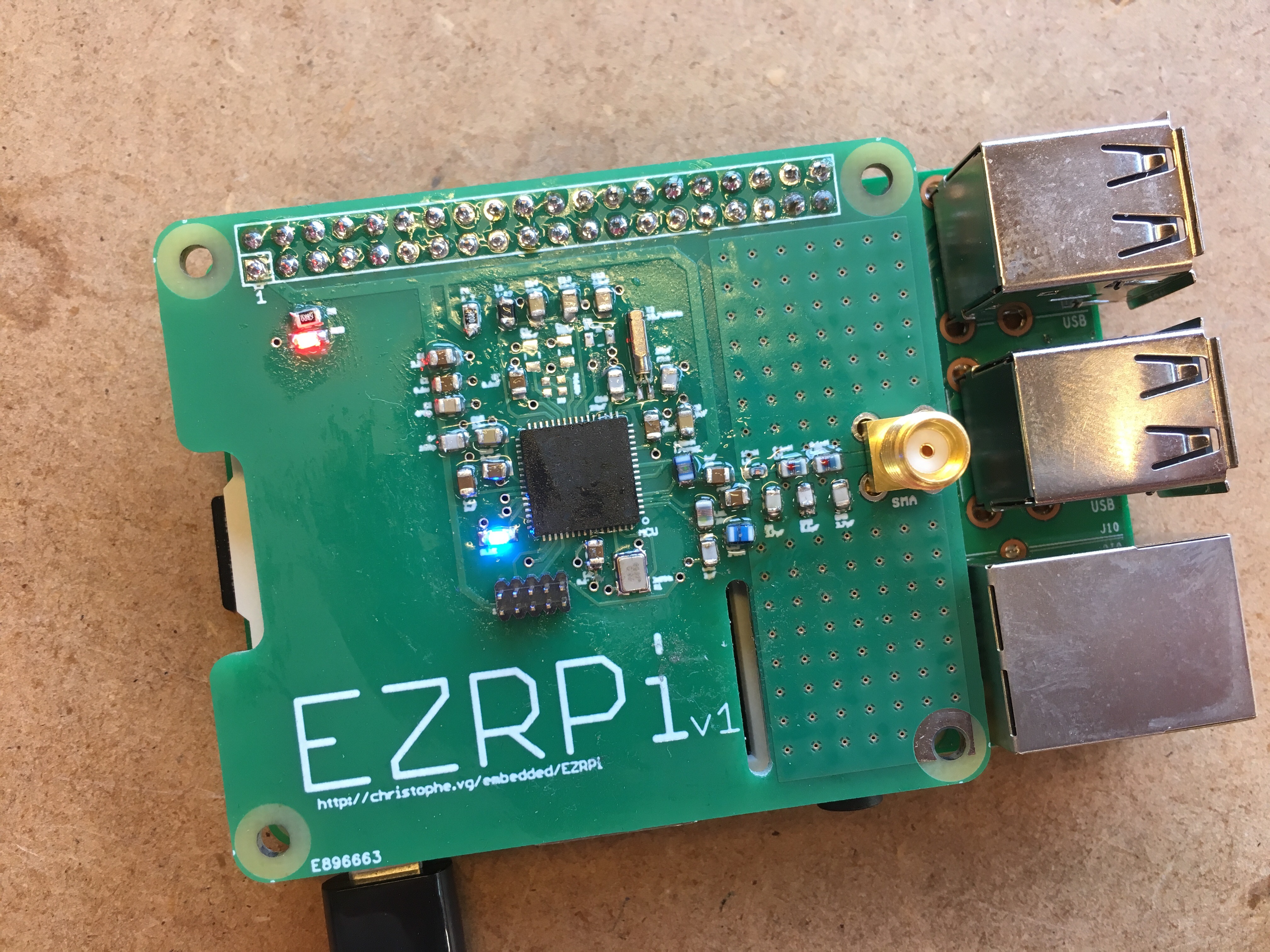
Version 1
On Thursday March 30, I was able to assemble the first EZRPi.
The design includes a standard 868MHz setup of the EZR32 and two LEDs for minimal debugging/feedback.
The board is a 2-layer PCB based on the official Raspberry Pi HAT board specification.
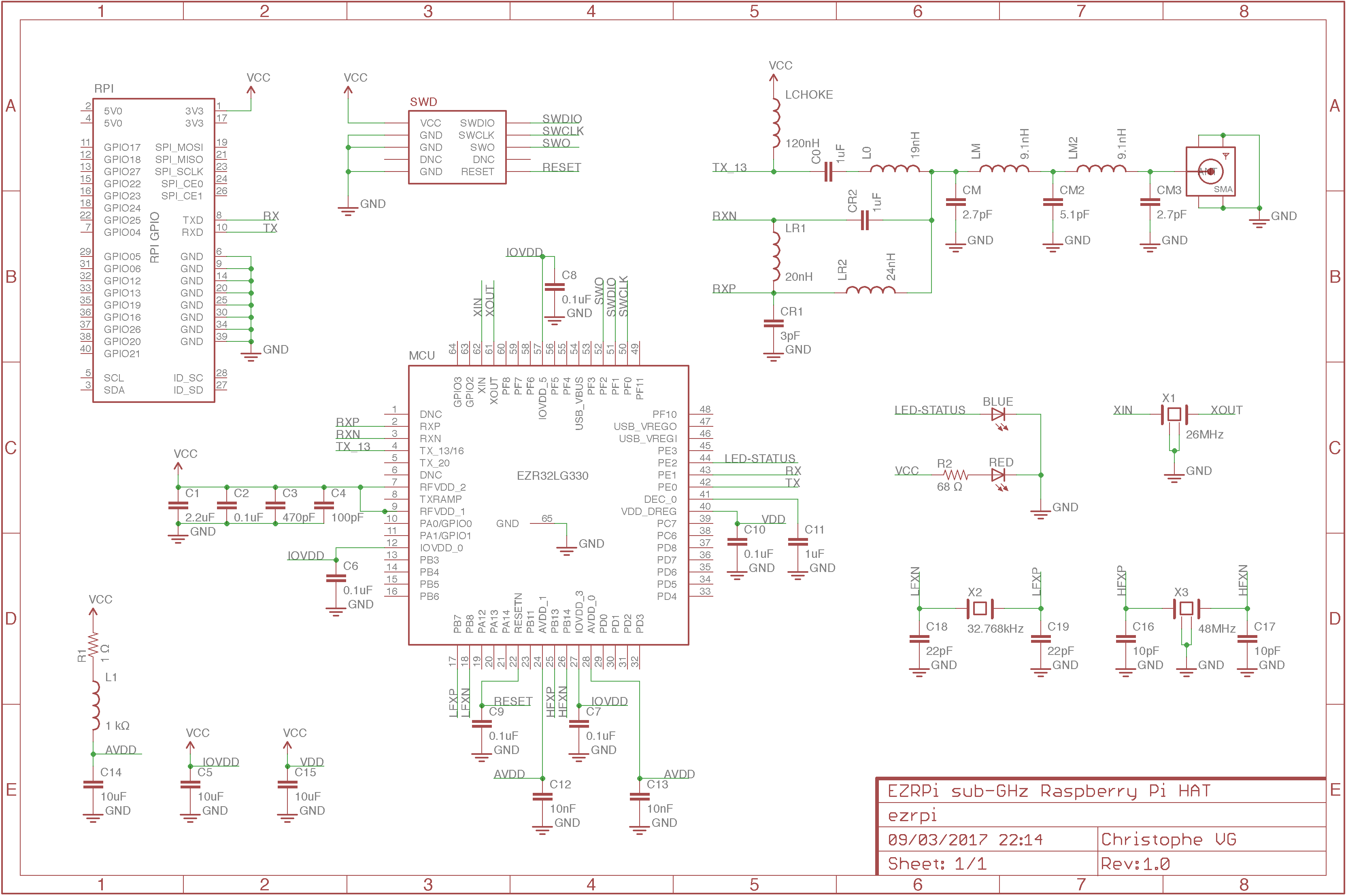
Schematic
The schematic is a verbatim implementation of what could be called a reference design, except for the fact that you have to bring together information from several resources.
- AN0002 - EFM32 and EZR32 hardware design considerations ↗
- AN0016 - EFM32 oscillator design considerations ↗
- AN627 - si4x6x and EZR32 low power pa matching ↗
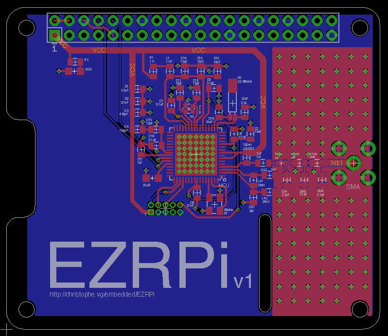
Board Layout
A board layout with RF signals is not your average PCB and requires some special care. Basically you really need to apply some best practices, that otherwise you could get away with. (With RF signals you can get away with it also, but you’ll loose performance and in RF terminology that means distance, and distance is what you’ll probably want ;-))
Some excellent general information on designing RF and Mixed signal boards can be found in Maxim’s tutorial 5100 ↗.
A few rules and their application I learned and applied:
Fast In & Outs
Try to keep traces as short as possible, or at least make sure they’re highways.
- The entire bottom layer of the PCB is a ground plane. So with a simple via you can reach
GNDfrom (nearly) everywhere. - The
VCCtraces are constructed as a star topology - in this case starting from theVCCpin on the HAT header branching out at the top-left corner of the occupied zone of the PCB - and are relatively wide. - The ground plane beneath the MCU is connected to the ground plane on the bottom by means of a lot of vias.
- The same goes for an additional ground plane on the top layer, around the antenna region. See below for more info on that.
- Where
GNDis needed, don’t use traces to join multipleGND-dependencies. Just use a via to go straight from every component toGND.
50Ω & co
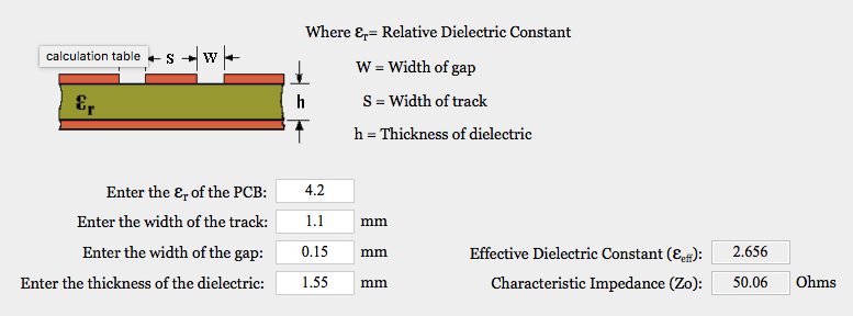
The traces going to the antenna are important. Their impedance needs to be (as close as possible to) 50Ω. Practically, this is needed for the last part, from the last inductor/capacitor on the right to the SMA connector itself.
To control the impedance, we need to calculate the width of the trace. There are some nice online calculators that help. Because I’ve added an additional top-layer ground plane around the antenna area, I’ve created a so called Coplanar Waveguide. In this case this allowed for a smaller trace width, which was needed because of the limited space between the GND pins of the SMA connector. Using one of the available online calculators ↗, I was able to limit the width of the trace to 1.1mm, resulting in a 50,06Ω trace.
Although there are already many vias connecting the top layer ground plane and the bottom layer ground plane, it is important to make sure that along the 50Ω trace, there are vias close-by, the so called via fences.
Good enough for now ;-)
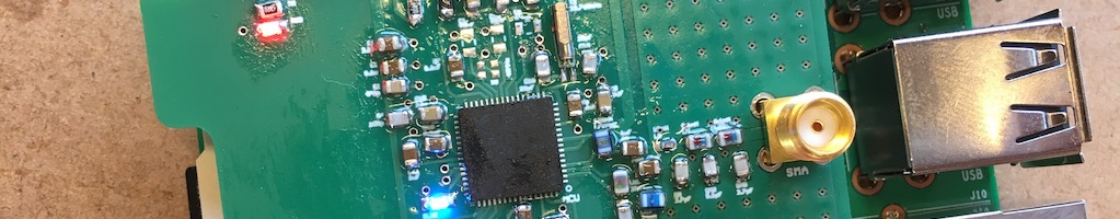
Hand-Soldering the First Board
I did some hand-soldering of SMD components before, but this design included another challenge: the QFN64 package ↗. I found the following great video, showing how to do it.
Something I didn’t expect was that on my first go, it would actually work out so well. Including the snapping back ;-)
Having ordered an incorrect blue LED, I also had to solder a 0603 package. But that and a 0402 packaged inductor both also went smooth.
Adding Software
To test the first assembled EZRPi, I implemented the mother of all programs, the embedded hello world counterpart: blink ↗ using the standard Gecko SDK ↗.
I hooked up the EZRPi to my desktop power supply and turned it on. At first things looked optimistic, J-Link detected the MCU, great!
Found SWD-DP with ID 0x2BA01477
AP-IDR: 0x24770011, Type: AHB-AP
AHB-AP ROM: 0xE00FF000 (Base addr. of first ROM table)
Found Cortex-M3 r2p1, Little endian.
FPUnit: 6 code (BP) slots and 2 literal slots
CoreSight components:
ROMTbl 0 @ E00FF000
ROMTbl 0 [0]: FFF0F000, CID: B105E00D, PID: 000BB000 SCS
ROMTbl 0 [1]: FFF02000, CID: B105E00D, PID: 003BB002 DWT
ROMTbl 0 [2]: FFF03000, CID: B105E00D, PID: 002BB003 FPB
ROMTbl 0 [3]: FFF01000, CID: B105E00D, PID: 003BB001 ITM
ROMTbl 0 [4]: FFF41000, CID: B105900D, PID: 003BB923 TPIU-Lite
ROMTbl 0 [5]: FFF42000, CID: B105900D, PID: 003BB924 ETM-M3
Cortex-M3 identified.
But when I tried to upload an image or tried to erase the device. I just got errors.
**************************
WARNING: CPU could not be halted
**************************

...

****** Error: Failed to restore target. RAMCode never stops
ERROR: Erase returned with error code -5.

...

****** Error: Timeout while erasing sectors, RAMCode did not respond in time
When after a few hours of digging around the Google indexes, I was about to give up. Since there were no shorts, I decided to mount it on an actual Raspberry Pi and give see what it looked like once, before starting soldering a second one. For fun I decided to try and program it once more… and behold… Everything went smooth as a baby.
Downloading file [blink/blink.bin]...
Comparing flash   [100%] Done.
Erasing flash     [100%] Done.
Programming flash [100%] Done.
Verifying flash   [100%] Done.
J-Link: Flash download: Flash programming performed for 1 range (6144 bytes)
J-Link: Flash download: Total time needed: 0.184s (Prepare: 0.066s, Compare: 0.004s, Erase: 0.000s, Program: 0.103s, Verify: 0.001s, Restore: 0.009s)
O.K.
In hindsight I think that only hooking up one of the 8 Ground pins of the Raspberry Pi header, wasn’t enough to give it a stable
GNDduring programming. 99% of the time it’s a GND problem!
And so, all of a sudden the EZRPi was alive…
Great. Time to test the RF part.
OSS-7 Support
As of Friday March 21 ↗, the Dash7 Open Source Stack ↗ includes a platform definition for the EZRPi - by yours truly ;-). This makes it super-easy to add Dash7 support to the Raspberry Pi.
$ git clone https://github.com/MOSAIC-LoPoW/dash7-ap-open-source-stack
Cloning into 'dash7-ap-open-source-stack'...
remote: Counting objects: 39483, done.
remote: Compressing objects: 100% (291/291), done.
remote: Total 39483 (delta 164), reused 0 (delta 0), pack-reused 39191
Receiving objects: 100% (39483/39483), 71.42 MiB | 8.46 MiB/s, done.
Resolving deltas: 100% (27893/27893), done.

$ cd dash7-ap-open-source-stack

$ mkdir build

$ cd build

$ cmake ../stack/ \
        -DCMAKE_TOOLCHAIN_FILE=../stack/cmake/toolchains/gcc-arm-embedded.cmake \
        -DPLATFORM=EZRPi \
        -DAPP_SENSOR_PUSH=on \
        -DFRAMEWORK_LOG_ENABLED=yes \
        -DFRAMEWORK_DEBUG_ASSERT_MINIMAL=y
-- Cross-compiling using gcc-arm-embedded toolchain
-- Cross-compiling using gcc-arm-embedded toolchain
-- The C compiler identification is GNU 4.9.3
-- The CXX compiler identification is GNU 4.9.3
-- Detecting C compiler ABI info
-- Detecting C compiler ABI info - failed
-- Detecting C compile features
-- Detecting C compile features - failed
-- Detecting CXX compiler ABI info
-- Detecting CXX compiler ABI info - failed
-- Detecting CXX compile features
-- Detecting CXX compile features - failed
-- detected supported platforms: EFM32GG_STK3700 EFM32HG_STK3400 EZR32LG_Octa EZR32LG_USB01 EZR32LG_WSTK6200A EZRPi OCTA_Gateway stm32f4_discovery
-- selected platform: EZRPi
-- The ASM compiler identification is GNU
-- Found assembler: /usr/local/bin/arm-none-eabi-gcc
-- Added chip ezr32lg
-- Added chip si4460
-- Configuring done
-- Generating done
-- Build files have been written to: /Users/xtof/dash7-ap-open-source-stack/build

$ make
Scanning dependencies of target CHIP_SI4460
[  1%] Building C object framework/hal/platforms/platform/chips/si4460/CMakeFiles/CHIP_SI4460.dir/si4460.c.obj
...
[ 98%] Building C object apps/sensor_push/CMakeFiles/sensor_push.elf.dir/version.c.obj
[100%] Linking C executable sensor_push.elf
[100%] Built target sensor_push.elf

$ make flash-sensor_push
[ 14%] Built target d7ap
[ 22%] Built target CHIP_SI4460
...
Downloading file [sensor_push.bin]...
Comparing flash   [100%] Done.
Erasing flash     [100%] Done.
Programming flash [100%] Done.
Verifying flash   [100%] Done.
J-Link: Flash download: Flash programming performed for 3 ranges (77824 bytes)
J-Link: Flash download: Total time needed: 1.960s (Prepare: 0.052s, Compare: 0.062s, Erase: 0.933s, Program: 0.896s, Verify: 0.008s, Restore: 0.007s)
O.K.

Loading binary file sensor_push.bin
Reading 81476 bytes data from target memory @ 0x00000000.
Verify successful.

Reset delay: 0 ms
Reset type NORMAL: Resets core & peripherals via SYSRESETREQ & VECTRESET bit.


Script processing completed.

[100%] Built target flash-sensor_push
The EZRPi has been tested alongside the EZR32LG_USB01 ↗ dongle and bidirectional communication was achieved!
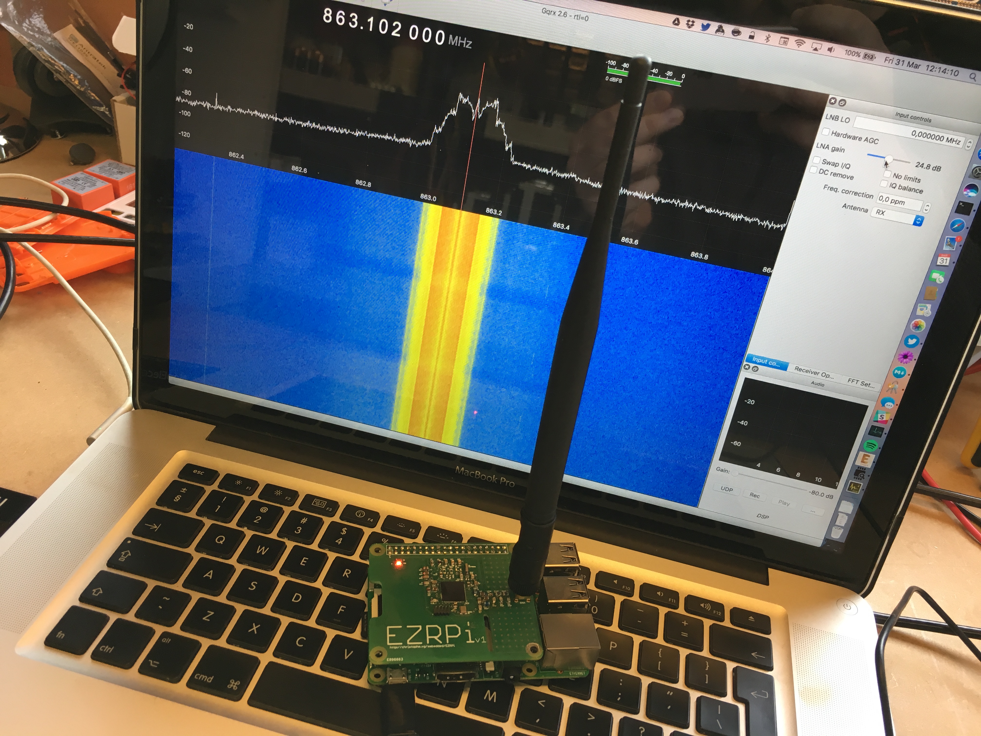
If you choose the
continuous_txapp and open up an SDR… you can see it in action.
More to come …